

Load Inverters
Mechanical Upenders
Hydraulic Upenders
Coil Mounting Systems
Lift Tables
Die & Mold Handling Equipment


Technical Papers
Case Studies Archive by Title:
MILLENNIUM STEEL ARTICLE: Integrated Material Handling in a Steel Service Center
Inverting The Process
MILLENNIUM STEEL ARTICLE: Integrated Material Handling in a Steel Service Center
Describes how a West Bend custom designed handling system helped a steel service center cut process time by 50%, boost productivity by 75% and enhance safety. A PDF version of this article is available below with the permission of Millennium Steel which published the article in its 2004 edition. Click here to download the PDF of this article.
An article on this same topic was published in the July 2004 issue of The Fabricator.
Inverting The Process
The steel industry’s need to handle material quickly and safely, while eliminating product damage, makes the use of large industrial, hydraulic/mechanical inverters a standard fixture at many sites. These load inverters can stack sheared sheets so the cut edge is correctly oriented or can handle a 10,000-megawatt transformer being prepared for sandblasting. Such operations require minimal human intervention.
This paper will provide information about inverter designs, determining the correct size of the unit, equipment operation, and safety considerations, together with the correct integration of a hydraulic/mechanical inverter in a steel handling application.
Inverter Design, Basic Principles
Inverters, which hold and rotate a load 180-degrees, require a sufficient clamping force to hold the load safely. This clamping force is created by a hydraulic scissors action that imposes a perpendicular force on the load (Figure 1.)
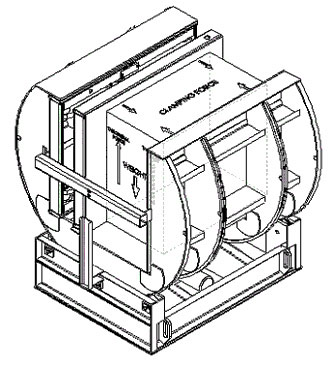
Figure 1 – Inverter Free Body Diagram
The clamping pressure sets up a tangential force that is coupled with a friction coefficient to overcome the weight of the load. Figure 1 shows the load in the worst-case scenario, with the full effect of gravity maximizing the required clamping force. The friction coefficient between the different layers of the load is critical in determining the necessary clamping force. A stack of lubricated aluminum sheets with wooden pallets at the top and bottom is a good example of a multi-layered load. This configuration is frequently seen in the automotive industry. The friction coefficient between the rough wood of the pallets and the aluminum sheets is high, 0.35, so a relatively small clamping force is required for this layer. However, the coefficient between each lubricated aluminum sheet can be as low as 0.08, which would require a clamping force of as much as five times the weight of the load (Figure 2). In this scenario, slippage of the sheets is more likely to occur in the center of the load between the aluminum sheets rather than at the pallet/sheet or pallet/scissors table interface. The inverter’s clamping force needs to be sized for the interface with the smallest friction coefficient.
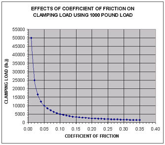
Figure 2
If the process line needs to invert only single units of product, such as dies, finished products, or tightly banded materials, the clamping force can usually be reduced, since the only sliding interfaces would be between the product and the clamp tables. Methods that can be used to secure the load and reduce the clamping force required to safely invert the material include applying high friction surfaces, installing guides, and having automatic alignment pins to interface with the load once it is placed on the clamp tables.
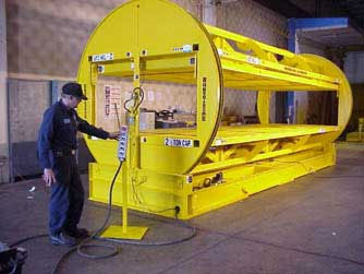
Figure 3 – Barrel inverter
Barrel Inverters
There are two main types of inverters, barrel and C-frame. Figure 3 is an example of a barrel inverter. The load is placed in one end or side of the barrel, the load is clamped, and a drive motor inverts the barrel 180 degrees. The advantage of this type of inverter is that it can be loaded and unloaded from one side, saving the forklift operator time since the truck does not need to be repositioned to remove the inverted load.
Another important factor is structural strength. The circular sections of the inverter can be made out of single profiled plates, reducing the potential for fatigue cracking in the highly stressed areas of each plate.
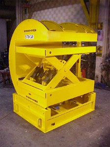
Figure 4 – C-frame Inverter
C-frame Inverters
The C-frame inverter is shown in Figure 4. The C-frame’s biggest advantage is flexibility as they can be used to invert materials of many different lengths because the ends of the load can extend beyond the ends of the inverter, along its axis of rotation. Operators can also load C-frames easily from three different sides. After inversion, the inverter can then be unloaded on the opposite side from where it was loaded. Alternatively, a rotator or bearing assembly can be placed under the inverter to allow loading and unloading from the same position. In this instance, the manufacturing engineer must carefully consider the circle of rotation of the inverter plus the load material, especially if the load extends out the sides of the inverter.
If it is properly centered in a C-frame inverter, the load can extend out the sides since the center-of-gravity (CG) does not shift with respect to the axis of rotation, only with the width of the load. Hence, if the load extends out the front, the CG may be outside the design basis and equipment damage may occur. It is important to train the operators to understand that the load needs to be properly centered on the inverter. An easy operator interface tool is to paint a target on the clamping tables to provide a visible positioning aide.
Specific Design Considerations
The rotation of the inverter cylinder is normally accomplished by a gear motor with a fast acting integral brake, coupled to a chain and sprocket mechanism. Rotation can also be achieved with hydraulic motors, friction rollers or other rotational drive systems. The rotational drive system should be sized, based on the moment arm created by the sum of the centers-of-gravity of both the inverter and the load, coupled with a sufficient margin to overcome static friction, starting torque and dynamic loading. The actual load size and location of the CG need to be clearly stated in the design, so there is no confusion between the manufacturer and the user. The drive or inverter can be damaged if the CG of the load is not positioned within the design envelope.
Rarely does a manufacturing line continuously produce the same size material, so the inverter needs to be able to handle loads of different sizes. The largest and smallest load heights will determine the clamping range of the clamp tables. The largest raw material to be inverted plus the height of the top and bottom pallet, or other material-handling device, normally defines the height of the inverter opening. An additional two to four inches of clearance height is advisable to allow for forklift maneuverability or conveyor space.
For a barrel style inverter, the maximum length must be defined, but with a C-frame inverter, this dimension is usually only limited by the capacity of the inverter and the floor space around the inverter. The minimum length of the load needs to be established for some designs, since the clamping platforms may be able to deflect around the ends of a load that is too short. The deflection of the clamping platform can create high point loading which can damage both the material and the inverter. Adjustable pressure control is a design enhancement that can eliminate this problem.
As the clamping force is directly proportional to the weight of the load being inverted, for an inverter that has a large capacity range, the clamping force at the maximum capacity may be too high and cause damage to a small or lightweight product. Using a combination of hydraulic control valves, pressure transducers, and analog inputs to a programmable logic controller (PLC), the manufacturer can develop a control system to allow the operator to select the correct clamping force required for a specific load, based on the weight of that load.
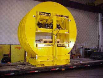
Figure 5 – Automotive Barrel Inverter
Hydraulic fluid needs to be introduced into the rotating cylinder through hose and fluid couplings. In Figure 5, dual, rigidly mounted swivel joints connected to flexible hosing create the clamping/unclamping hydraulic flow paths. Similarly, electrical connections to the rotating cylinder can be through swivel connections or through an electrical cable reel. With electrical connections, the limiting components are the number of conductors that are needed on the rotating cylinder. For inverters on process lines (Figure 6), the combination of powered conveyors and sensors tends to make an electric cable reel the only option.
For automated systems, conveyors frequently perform loading and unloading functions. Powered conveyors, located on both clamping platforms, allow the control system to automatically introduce the material to the inverter and discharge after inversion. Sensors, such as photo-eyes or ultrasonic sensors, can be used to properly align the material in the center of the inverter before inversion.
Additional sensors should be installed for safety on the outside edges of the rotating conveyors to ensure that no material extends beyond the inverter before rotation. The height of the conveyors, at the point of introduction and discharge, needs to be aligned with the conveyors inside the inverter.
The inverter shown in Figure 6 allowed the material to be introduced into one end, inverted, and then discharged out either end, based on a command from the control system. This dictated that the unit be designed so that all of the conveyors were at the same height when ready to operate. The conveyor rollers are an additional design consideration. These need to accommodate not only the weight of the load but also the clamping force exerted by the inverter. Stronger rollers inside the inverter, compared to the rollers outside the inverter, compensate for the higher forces and ensure long life.
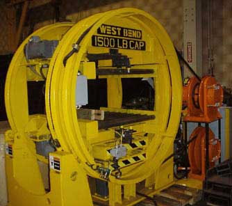
Figure 6 – Process Line Inverter
Safety
A typical automotive industrial inverter has a capacity of 15,000 pounds and a clamping force of 75,000 pounds. With these high loads, plus the weight of the cylinder rotating in 20 seconds, personnel safety is a crucial factor and must be designed into the unit as an integral feature. Numerous safety innovations can be included. The following are strongly recommended:
Safety Pins and Stops
The rotating cylinder and the clamp tables should have safety pins that can be used during maintenance. These pins can be designed to be padlocked in place for a Lockout/Tagout system.
Hydraulic Safety Considerations
ANSI MH29.1 (American National Standards Institute) recommends a number of items that should be incorporated into the inverter. Among these issues are overload protection, velocity fuses, limits on maximum operating pressures, and end stops. Although this standard is for industrial scissors lifts, it is applicable to the clamping mechanism on many inverters.
Emergency Stop Buttons
Emergency stop buttons should be placed at all egresses from the inverter and on the operator panel. The E-stop should stop all motion, maintain power to the control system and maintain pressure control. When the unit is powered back up, motion should not resume until the operator has provided a positive initiating action.
ANSI/NFPA-70
Electrical wiring and equipment should meet or exceed the requirements of the National Electric Code (ANSI/NFPA-70), or local national standards.
Personnel Barriers
Light curtains or metal caging should be installed to prevent personnel from inadvertently coming near a unit during operation. The light curtains should be connected into the same circuit as the E-stop or similar device. The open perimeter distance required before allowing rotation to begin, should be approximately one to three yards.
Additional Safety Features
These include load sensors for verifying that the load is in the proper location, multiple pressure transducers to monitor pressures throughout the system, and operator lights or alarms.
Summary
The specification, installation and training processes associated with the purchase of an inverter constitute a significant capital project. For this reason, it is of vital importance that the integration of the inverter into a process line be thoroughly reviewed. Among the issues to be considered are the following:
- Current and future materials to be handled.
- Required flexibility.
- Method of loading and unloading.
Safe working procedures.
Planning process integration up-front will ensure that the hydraulic/mechanical inverter can provide significant productivity and quality enhancements.
Products | Custom Engineering | About Us | Technical Papers | Press Releases | Case Studies | Request a Quote | Contact Us | Home